
Para produsen Vietnam dapat merencanakan sistem penyimpanan energi komersial dan industri (C&I) dengan lebih andal dengan memulai dari data beban terukur, output tenaga surya atap, jadwal produksi, dan skenario pertumbuhan yang realistis. Baterai harus dirancang untuk tugas operasional yang ditentukan – seperti konsumsi sendiri tenaga surya, pengendalian beban puncak, atau dukungan beban kritis – daripada dipilih hanya berdasarkan kapasitas nominal saja.
EPOTR Menyediakan peralatan penyimpanan energi untuk perumahan dan komersial, inverter, elektronika daya, dan solusi kontrol terkait. Untuk proyek pabrik, pembahasan yang bermanfaat adalah bagaimana kapasitas baterai, konversi daya, pendinginan, komunikasi, dan ekspansi di masa depan dapat dikombinasikan di sekitar profil kelistrikan pabrik.
Bagaimana Pertumbuhan Produksi Seharusnya Dikonversi Menjadi Kewajiban Penyimpanan?
Rencana perluasan pabrik biasanya mengubah lebih dari sekadar konsumsi energi tahunan. Pergeseran shift baru dapat menggeser permintaan ke malam hari, kompresor tambahan dapat meningkatkan puncak permintaan jangka pendek, dan susunan panel surya di atap yang lebih besar dapat menciptakan surplus energi yang lebih besar di siang hari. Setiap perubahan memengaruhi baterai secara berbeda. Sebelum membahas kapasitas, pabrik harus mengumpulkan data interval setidaknya beberapa minggu dan menandai akhir pekan, periode pemeliharaan, beban musiman, dan penghentian operasional yang tidak normal.
| Masukan Perencanaan | Apa yang Harus Direkam | Mengapa Ini Penting |
| Beban jaringan | Data permintaan 15 menit atau lebih halus | Menunjukkan besaran puncak, durasi, dan waktu |
| Panel surya atap | Kurva generasi dan sejarah pembatasan produksi | Menunjukkan berapa banyak energi yang sebenarnya tersedia untuk pengisian daya. |
| Rencana produksi | Jalur produksi baru, perubahan shift, dan beban motor yang besar. | Mencegah ukuran menjadi terlalu kecil setelah ekspansi. |
| Beban kritis | Daya kW yang dibutuhkan dan durasi cadangan | Memisahkan kebutuhan ketahanan dari tugas penghematan biaya. |
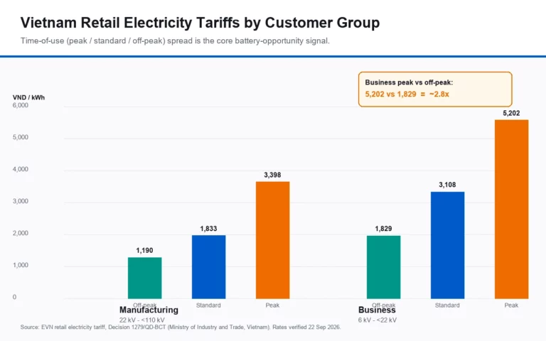
| Struktur tarif | Biaya permintaan dan periode penggunaan waktu | Mendefinisikan jendela pengiriman ekonomi. |
Hasilnya harus berupa profil beban kerja, bukan target kWh tunggal. Satu pembangkit mungkin membutuhkan satu pelepasan daya besar di malam hari, sementara pembangkit lain membutuhkan beberapa pelepasan daya singkat untuk menjaga koneksi jaringan di bawah batas yang disepakati. Kedua proyek tersebut dapat menggunakan kapasitas energi yang serupa tetapi membutuhkan daya inverter dan logika kontrol yang berbeda.
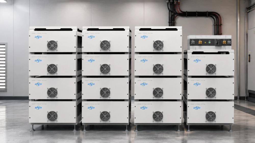
Apa yang Ditawarkan Konfigurasi ESS C&I 241kWh?
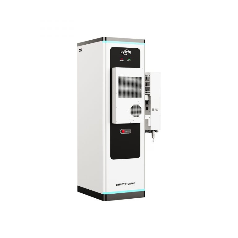
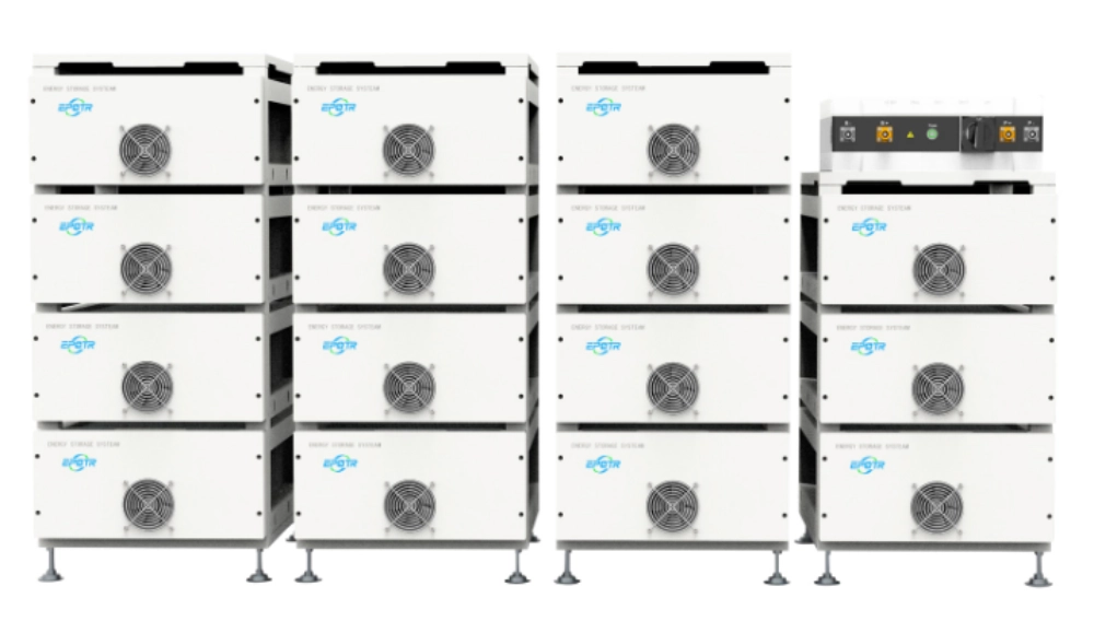
Yang dirujuk Solusi ESS C&I Menggunakan energi sistem sebesar 241 kWh dan energi yang dapat digunakan sebesar 216,9 kWh, dengan tegangan sistem nominal 768 V dan kedalaman pengosongan yang direkomendasikan sebesar 90%. Pendinginan kipas cerdas, komunikasi CAN dengan BMS, dan antarmuka komunikasi TCP, RS485, dan CAN mendukung integrasi dengan konversi daya dan peralatan kontrol lokasi.
Angka-angka tersebut membantu menentukan batas operasional, tetapi tidak menggantikan rekayasa proyek. Energi yang dapat digunakan harus diperiksa terhadap kerugian sistem, status pengisian cadangan, suhu lingkungan, dan degradasi yang diharapkan. Panduan masa pakai siklus yang dinyatakan minimal 8.000 siklus pada 25°C di bawah kondisi pengujian yang ditentukan paling berguna ketika strategi pengiriman yang diusulkan dibandingkan dengan kondisi tersebut, bukan diperlakukan sebagai janji masa pakai universal.
Di mana sistem tersebut dapat menciptakan nilai pabrik yang terukur?
Mode operasi terkuat adalah mode yang mampu mengatasi kendala kelistrikan yang berulang. Mencoba menggabungkan setiap kemungkinan kasus penggunaan sejak hari pertama seringkali membuat kontrol lebih sulit divalidasi dan penghematan lebih sulit diukur.
Manfaatkan Energi Surya Atap yang Seharusnya Diekspor atau Dikurangi
Ketika permintaan produksi menurun selama jam istirahat makan siang, akhir pekan, atau periode sepi musiman, pembangkitan energi dari atap dapat melebihi konsumsi di lokasi. Mengisi daya baterai selama interval tersebut memungkinkan lebih banyak output energi surya untuk digunakan nanti. Perhitungan harus menggunakan surplus aktual setelah beban pabrik, bukan output maksimum yang tertera pada panel surya.
Batasi Puncak Produksi Jangka Pendek
Mesin las, kompresor, pendingin, pompa, dan peralatan batch dapat menciptakan lonjakan daya yang hanya berlangsung beberapa menit. Sistem penyimpanan energi (ESS) untuk komersial dan industri (C&I) dapat melepaskan daya selama kejadian tersebut jika daya dan respons kontrol PCS mencukupi. Aplikasi ini sensitif terhadap daya: baterai besar dengan inverter yang ukurannya kurang memadai mungkin menyimpan energi yang cukup tetapi tetap gagal mengurangi lonjakan daya.
Melindungi Proses Terpilih Selama Gangguan Jaringan Listrik
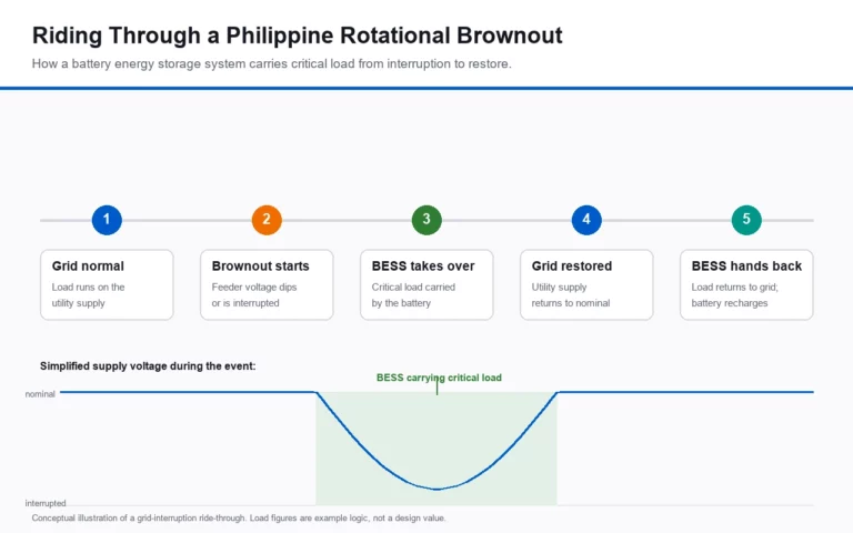
Dukungan beban kritis harus difokuskan pada peralatan yang gangguan operasionalnya menyebabkan pemborosan, waktu restart yang lama, atau masalah keselamatan. Kontrol, server, stasiun pengujian, ventilasi tertentu, dan pompa proses mungkin perlu diprioritaskan, sementara beban kenyamanan yang besar tetap berada di luar jalur cadangan. Pendekatan ini memperpanjang waktu operasional yang bermanfaat tanpa mengubah proyek menjadi pengoperasian pabrik secara terisolasi sepenuhnya.
Menambah Kapasitas Seiring dengan Ekspansi Produksi
Desain bertahap dapat mengurangi risiko pembelian berdasarkan perkiraan lima tahun yang tidak pasti. Fase pertama dapat menangani kurva beban yang telah diverifikasi, sementara ruang panel distribusi, arsitektur komunikasi, dan tata letak fisik menyediakan ruang untuk kabinet selanjutnya. Ekspansi jauh lebih mudah jika dipertimbangkan selama desain proteksi dan kabel awal.
Detail Integrasi Mana yang Menentukan Apakah ESS Berfungsi dengan Lancar?
Pisahkan Energi Baterai dari Daya PCS
Energi baterai diukur dalam kWh; daya keluaran sesaat diukur dalam kW. Pembangkit listrik harus menentukan baik periode pelepasan daya terlama maupun periode daya tertinggi. Proyek yang ditujukan untuk pergeseran energi surya mungkin membutuhkan lebih banyak energi, sementara proyek yang ditujukan untuk pengurangan beban puncak mungkin membutuhkan daya lebih tinggi untuk waktu yang lebih singkat.
Konfirmasikan Komunikasi BMS, PCS, dan EMS Sebelum Pemasangan
Nama protokol saja tidak menjamin pengoperasian plug-and-play. Tim teknik harus mengkonfirmasi titik data, izin perintah, penanganan alarm, batas status pengisian daya, sinkronisasi waktu, dan perilaku fail-safe. Daftar sinyal dan matriks tanggung jawab yang jelas mencegah penundaan komisioning antara pemasok baterai, PCS, meteran, dan EMS pabrik.
Rancang Ruangan dengan Mempertimbangkan Suhu, Akses, dan Perawatan.
Penataan ruang kabinet, aliran udara, jalur kabel, drainase, pemisahan api, dan jarak bebas servis harus dipertimbangkan pada gambar tata letak. Sistem yang secara matematis sesuai pun masih bisa sulit dipasang jika pintu tidak dapat terbuka sepenuhnya atau teknisi tidak dapat menjangkau filter, terminal, dan titik isolasi.
Komisi dengan Skenario Operasi Nyata
Penerimaan pabrik harus mencakup perintah pengisian dan pengosongan, hilangnya komunikasi, kegagalan meteran, penghentian darurat, batas status pengisian rendah dan tinggi, dan pemulihan setelah kejadian jaringan listrik. Pabrik juga harus memverifikasi bahwa peralatan produksi tidak terpapar transisi tegangan atau frekuensi yang tidak diinginkan selama perubahan mode.
Bagaimana Seharusnya Produsen Membandingkan Konfigurasi yang Bersaing?
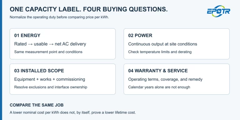
Perbandingan profesional harus menormalkan energi yang dapat digunakan, daya PCS, konsumsi tambahan, kondisi garansi, cakupan komunikasi, peralatan keselamatan, batas pengiriman, dan dukungan komisioning. Membandingkan hanya harga kabinet dapat menyembunyikan perbedaan besar dalam hal yang masih harus disediakan oleh kontraktor EPC.
Selain itu, ada baiknya untuk memodelkan setidaknya tiga skenario: produksi saat ini, ekspansi yang diumumkan, dan skenario pertumbuhan tinggi yang konservatif. Sistem yang direkomendasikan harus berkinerja baik dalam ketiga skenario tersebut tanpa bergantung pada keluaran energi surya yang tidak realistis atau siklus harian yang sempurna. Dengan skenario-skenario tersebut, produsen dapat melakukan evaluasi. Sumber daya penyimpanan energi komersial EPOTR terhadap beban kerja dan rencana integrasi pabrik yang telah selesai.
Kesimpulan
Para produsen di Vietnam harus memperlakukan penyimpanan energi komersial dan industri (C&I) sebagai sistem operasi yang terhubung dengan produksi, energi surya, tarif, dan proteksi listrik. Ukuran yang tepat adalah konfigurasi yang menjalankan tugas tertentu pada kurva beban riil sambil memberikan ruang yang masuk akal untuk ekspansi.
Ketika energi yang dapat digunakan, daya PCS, komunikasi, tata letak fisik, dan uji coba pengoperasian disepakati sebelum pengadaan, energi surya atap dan pertumbuhan produksi dapat dikelola dengan jauh lebih sedikit spekulasi.
FAQ (Pertanyaan umum)
Q1: Apakah 241 kWh Cukup untuk Pabrik Berukuran Sedang?
A: Itu tergantung pada kurva beban dan tujuan pengoperasian. Sistem 241 kWh mungkin cocok untuk jendela pengendalian beban puncak yang singkat atau beban kritis tertentu, tetapi pergeseran energi surya yang lebih besar atau tugas cadangan jangka panjang mungkin memerlukan kapasitas tambahan.
Q2: Haruskah Ukuran Baterai Ditentukan Berdasarkan Kapasitas Panel Surya Atap?
A: Tidak. Gunakan surplus energi surya yang terukur setelah konsumsi pabrik di siang hari. Panel surya atap 800kW tidak menghasilkan daya pengisian sebesar 800kW ketika beban produksi sudah menggunakan sebagian besar daya yang dihasilkan.
Q3: Data Apa yang Harus Dibagikan Sebelum Konfigurasi?
A: Berikan data beban interval, pembangkitan PV, periode tarif, kW beban kritis, waktu cadangan yang dibutuhkan, pertumbuhan produksi yang direncanakan, ruang instalasi yang tersedia, dan informasi tentang peralatan sakelar dan transformator yang ada.
Q4: Mengapa Integrasi EMS Penting?
A: Sistem manajemen energi (EMS) menentukan kapan baterai diisi dan dikosongkan. Data meteran yang buruk, pemetaan protokol yang tidak lengkap, atau prioritas kontrol yang tidak jelas dapat mencegah sistem memberikan pengurangan beban puncak yang direncanakan atau konsumsi energi surya sendiri.
Q5: Dapatkah ESS C&I Diperluas di Kemudian Hari?
A: Ekspansi dapat dilakukan jika desain awal telah menyediakan kapasitas listrik, alamat komunikasi, ruang fisik, dan koordinasi proteksi. Menambahkan kabinet tanpa ketentuan tersebut dapat memerlukan pengerjaan ulang yang besar.